Home
Biography
Tables, Chairs
Cabinet Furniture
Beds, Built-ins, Other Work
Exhibitions, Galleries, News
Articles
Teaching and Student Work
Contact
Top of Page
Top of Page
Richard Jones Furniture
Making an oak refectory table
Dimensions: 2550 mm L X 1100 W X ~750 H (100-1/2" L X 43-3/8" W X 29-1/2" H)Material: Solid American white oak. In this workshop based photograph of the table, taken in December 2017, it is unfinished awaiting a polish selection by the client. If possible, the two photographs below will be replaced by ones of the finished piece in its final location. Made by me on a freelance contract basis for Tom Maxwell Furniture to their design.


Making the table top including clamped ends (aka breadboard ends)


Below. Attaching the clamped ends. The central M&T glued and cramped, and later reinforced with a cross pinning dowel or trunnel. The M&Ts at extremities of the clamped end are assembled dry. The tenon matches an overlong mortice thus allowing the tenon to slip side to side as the main table top expands and contracts seasonally. The dowels, driven upwards from the underside through the slots in the tenon hold the clamp tight at the shoulder line intersection of the clamped end and main panel. The dowels don't penetrate the table's top surface.
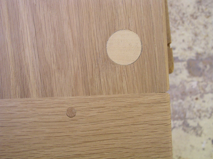
Below. Underside view of attached clamp showing tenon piercing dowel and large pale coloured dowel where the thread of a coach screw bites. The coach screw passes through the width of the clamp, and the necessary hole on the outer edge hidden by a thin strip of solid oak.
Below. A bit of skimming with hand planes precedes final sanding with a belt sander and a random orbital sander to 180 grit.


Below. The pedestals consist of five flattened boards glued together with urea formaldehyde adhesive, making it easier to set up the tools and guides to excavate the lower cross-grain coves.
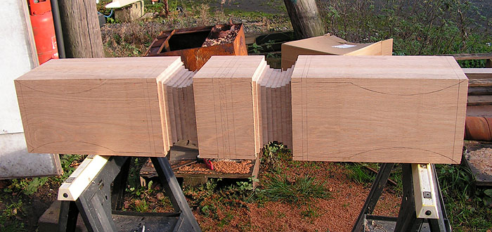
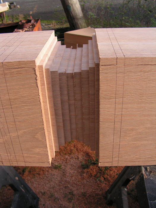
Below. Roughing out the cove profile with a router and a housing/ cross cutting guide or jig. Essentially just a series steps setting the router deeper as needed and moving the cross cut housing guide to suit.

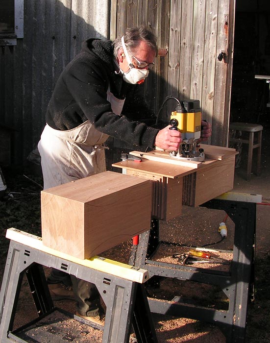
Below. Same housing guide, but the straight cutter used earlier replaced with a large diameter radius or cove bit.

Below. Getting closer to the required cove profile. Use of the radius cutter nearly complete.

Below. Long pedestal blank cut into its two individual pieces. It's possible in this image to make out the five laminated parts that make up the thickness. The blank came out at approximately 225 mm (8-7/8") square. The tangentially sawn boards used are arranged with all the end grain arcs in the same orientation, i.e., all the end grain 'smiles' (or 'frowns' if you prefer) align. Any future potential cupping will also therefore be aligned reducing the likelihood of glue line separation or splitting of the grain.

Below: bobbin sanding the cove profile.

Below. Bandsawing the waste of the long curved part of the pedestal. This was followed by some bobbin sanding plus sanding with a random orbital sander.

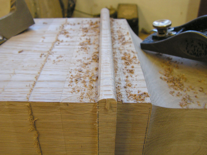
Below. Working one of the cross grain beads with a variety of small planes, followed by hand sanding.
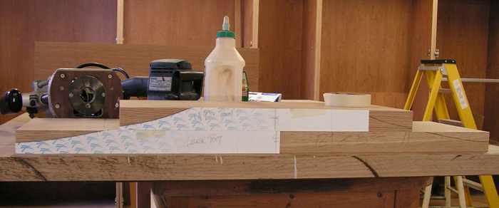
Below. Two pieces of wood 245 mm (~9-5/8") wide by 40 mm (~1-9/16") thick make up the foot. Two card templates were used to transfer the required profile to each foot part. A bandsaw cut the curves followed by sanding and assembly using PVA adhesive and screws.
Below. A clamped on an L shaped square of MDF helped hold the narrow foot part square to the bandsaw's table. A spokeshave and a random orbital sander smoothed out the bandsaw blade ripple left in the cut curved profile. The same general technique was used to create a simple straight bevel at the outer end of each bearer.



Below. Screw slot worked in a bearer with a router, two router cutters of different diameter and a side fence.



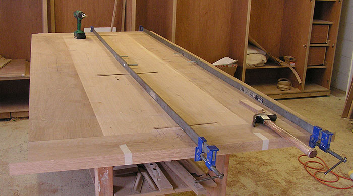
Four boards, two at 40 mm thick and two at ~20 mm thick edge jointed using urea formaldehyde adhesive (Cascamite).

Below.Stages in the making of the clamped ends.


Below. Extended slot in the end tenon to allow for expansion and contraction of the long main panel.

Below. Attaching the clamped ends. The central M&T glued and cramped, and later reinforced with a cross pinning dowel or trunnel. The M&Ts at extremities of the clamped end are assembled dry. The tenon matches an overlong mortice thus allowing the tenon to slip side to side as the main table top expands and contracts seasonally. The dowels, driven upwards from the underside through the slots in the tenon hold the clamp tight at the shoulder line intersection of the clamped end and main panel. The dowels don't penetrate the table's top surface.

Below. Underside view of attached clamp showing tenon piercing dowel and large pale coloured dowel where the thread of a coach screw bites. The coach screw passes through the width of the clamp, and the necessary hole on the outer edge hidden by a thin strip of solid oak.

Below. A bit of skimming with hand planes precedes final sanding with a belt sander and a random orbital sander to 180 grit.

Pedestal leg manufacturing stages.
Below. Paper profile.

Below. The pedestals consist of five flattened boards glued together with urea formaldehyde adhesive, making it easier to set up the tools and guides to excavate the lower cross-grain coves.


Below. Roughing out the cove profile with a router and a housing/ cross cutting guide or jig. Essentially just a series steps setting the router deeper as needed and moving the cross cut housing guide to suit.


Below. Same housing guide, but the straight cutter used earlier replaced with a large diameter radius or cove bit.

Below. Getting closer to the required cove profile. Use of the radius cutter nearly complete.

Below. Long pedestal blank cut into its two individual pieces. It's possible in this image to make out the five laminated parts that make up the thickness. The blank came out at approximately 225 mm (8-7/8") square. The tangentially sawn boards used are arranged with all the end grain arcs in the same orientation, i.e., all the end grain 'smiles' (or 'frowns' if you prefer) align. Any future potential cupping will also therefore be aligned reducing the likelihood of glue line separation or splitting of the grain.

Below: bobbin sanding the cove profile.

Below. Bandsawing the waste of the long curved part of the pedestal. This was followed by some bobbin sanding plus sanding with a random orbital sander.

Below. Working one of the cross grain beads with a variety of small planes, followed by hand sanding.

Making and shaping feet.
Below. Two pieces of wood 245 mm (~9-5/8") wide by 40 mm (~1-9/16") thick make up the foot. Two card templates were used to transfer the required profile to each foot part. A bandsaw cut the curves followed by sanding and assembly using PVA adhesive and screws.

Below. A clamped on an L shaped square of MDF helped hold the narrow foot part square to the bandsaw's table. A spokeshave and a random orbital sander smoothed out the bandsaw blade ripple left in the cut curved profile. The same general technique was used to create a simple straight bevel at the outer end of each bearer.


Final Assembly of pedestal legset to table top.
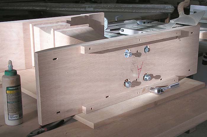
Below. Assembling the legset of foot, pedestal and bearer.
Two dowels at each end of the pedestal locate this to both the foot and
the bearer - they contribute nothing to strength acting merely as
guides for accurate positioning of the parts. Threaded inserts
installed into the pedestal are matched with M10 machine screws passing
through 13 mm diameter holes lock the parts together. A traditional
connection here would be a double or twin mortice and tenon, but on
this occasion I was asked to use this alternative. It's hard to know how this unconventional contemporary joinery solution will stand the test of time.


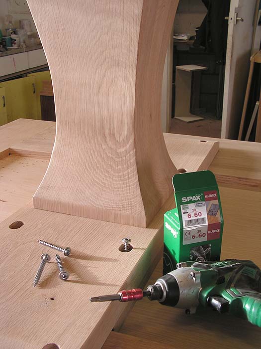
Attaching the legset to the table top.
Below. Screw slot worked in a bearer with a router, two router cutters of different diameter and a side fence.


Home Biography Tables, Chairs Cabinet Furniture Beds, Built-ins, Other Work Exhibitions, Galleries, News Articles Teaching and Student Work
Contact
Contact
© 2018 Richard Jones