Home
Biography
Tables, Chairs
Cabinet Furniture
Beds, Built-ins, Other Work
Exhibitions, Galleries, News
Articles
Teaching and Student Work
Contact
Richard Jones Furniture
Making a Tambour
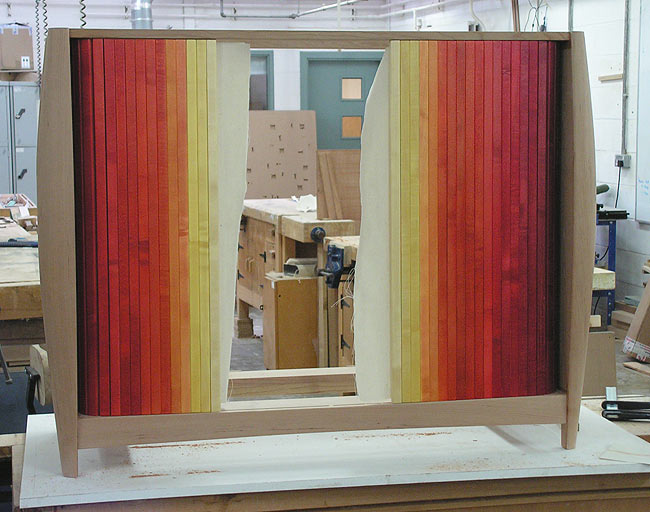
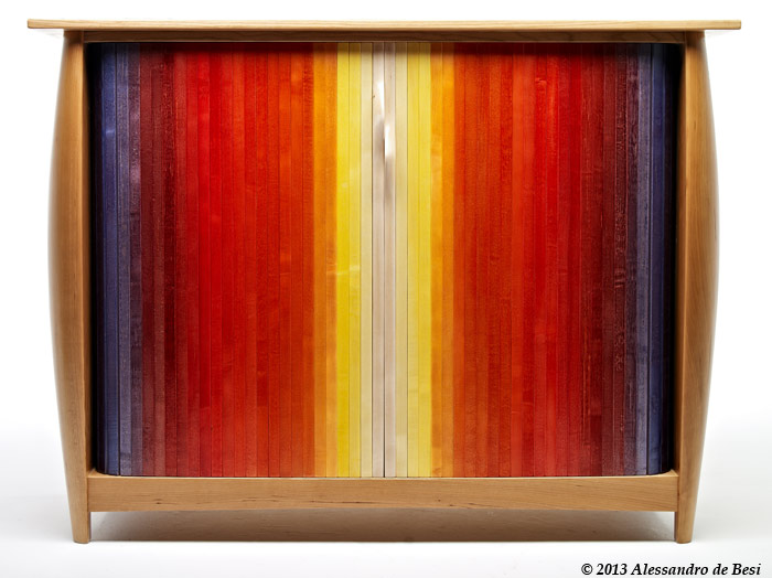
The tambour manufacture described here was for the cabinet Torpedore.Making a tambour for a cabinet can be challenging. There are several things that need to be just right for the tambour to run smoothly. The weight of the tambour itself can cause it to be heavy which may make it difficult to either open or close: if this is the case a way to solve the challenge is including a mechanism in the system to aid with either opening or closing. The cabinet itself must be square because if it isn't the grooves for the ends of the tambour's staves or slats will be non-parallel or misaligned resulting in the tambour running improperly, or worse still, not at all. Including a tambour in a cabinet's design means a loss of internal space because the tambour has to have somewhere to go, and there needs to be some sort of internal protective panel so that objects within the cabinet do not impede the tambour's movement. Having said that, including a tambour in the design does mean there aren't doors needing space within the room to open. On the other hand, there are design opportunities with tambours, as in this case, where each stave was dyed individually to create a gradation in colour from white, through yellow, orange, red, purple, blue to inky black.
What follows is essentially a photo-essay of the construction of the pair of tambours for the cabinet Torpedore. Comments are added where they aid clarity or help explain a technique.
Creating Grooves to Guide the Tambour
Work starts prior to manufacturing the tambour itself with construction of the cabinet, including the grooves for the ends of the tambour staves (or slats) to run in. In this case, because the pair of tambours run horizontally, appropriate grooves were cut in the underside of the cabinet top and on the upper side of the cabinet bottom. The grooves are 7 mm wide by 7 mm deep to take a 6 mm thick tongue 8 mm long. The purpose of the tongue being longer than the depth of the groove is so the weight of the tambour is carried by the end of the stave's tongue and not by the shoulder of the stave. This prevents the shoulder of the stave, at least in the short term, i.e., hopefully a few decades, wearing a groove in the upper face of the cabinet bottom. In the image below the rear of the cabinet bottom is in the foreground and it can be seen that the groove is gently angled towards a rebate which later locates the cabinet's back panel. The groove runs out into the rebate itself, just out of sight to the right of the photograph. The purpose of this run-out is so that the assembled tambour can slide into the cabinet from the rear.

It's hard to see in the photograph above, but as the groove turns the corners, its width increases to 8.5 mm whereas on the straight sections it is 7 mm wide. This allows each individual stave to pivot as it passes around the corner. As each stave negotiates its way around this curved section of the groove, the inside face behaves as a tangent line touching the circumference of a circle: the inside corner of the groove is a quarter arc of a circle' s circumference. The two edges of each stave pivot about the centre point of the stave's width, and each stave takes up the extra width in the groove. The groove for the tambour, and even the dovetails locating this panel to the end panels of the cabinet were worked on a CNC machine.
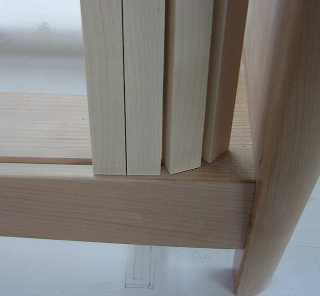
When construction of the basic cabinet was completed sample staves for the tambour were machined up, and a tongue worked on each end to fit into the grooves. Four staves were held together with some masking tape and test running followed, see the two images below.
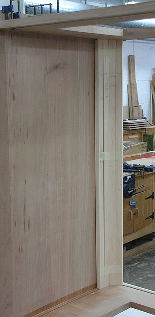
With
there being two tambours a means was required to prevent either of them
going beyond the centre point at the front of the cabinet. This was
achieved simply by stopping the grooves that guide the tambours just
before the centre point of the cabinet top and bottom, see below.
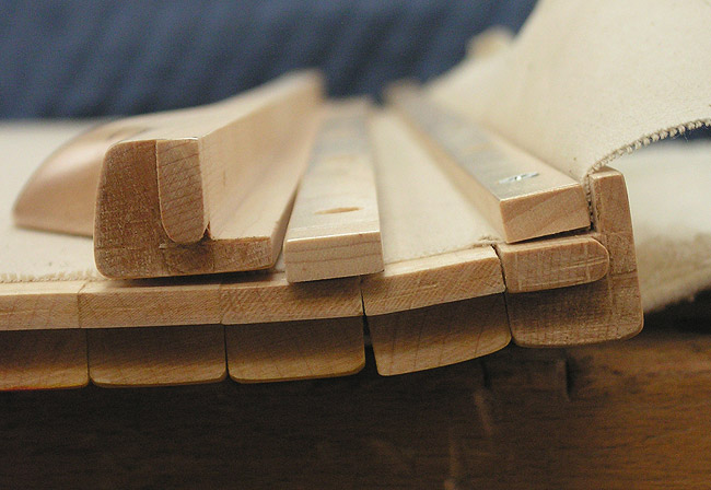
At about the same time as the 54 staves that make up the tambours were machined up, plus about ten extra staves to allow for rejection due to unacceptable warping, appearance, etc, the two central locking staves were made, carved, shaped and test fitted to the tambour grooves, below.
Dying and Polishing
With all the tambour staves made, they were hand planed to remove machine marks, then scraped, the sharp arris on edges knocked back, and sanded ready for dying and polishing. The purpose of polishing at this stage are threefold:
With all the tambour staves made, they were hand planed to remove machine marks, then scraped, the sharp arris on edges knocked back, and sanded ready for dying and polishing. The purpose of polishing at this stage are threefold:
- Firstly, because the intention was to effect a graduated colour change from the white of the hard maple at the centre of the cabinet through yellow, to orange, to red, to purple, to blue, and a blue black at the outer edges, the way chosen to accomplish this was to use Morrells 'Light Fast Dyes', which are spirit soluble, and apply them with a spray gun.
- Secondly, all the staves are eventually linked together using canvas glued on to the back face of the staves. So, with the show face and edges of each stave polished, any glue seeping between the staves during application of the backing canvas won't cause them to stick together.
- Thirdly, it's just hard to properly polish every part of an assembled tambour, so doing the job prior to assembly makes sense.
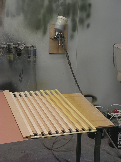
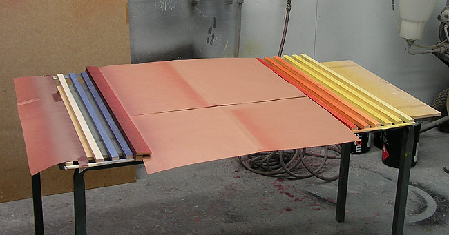
The
series of images below illustrate the dying procedure. At the left in
the first image is an L shaped shield made out of two pieces of MDF
simply tacked together which, as can be seen, lies over one of the
tambour staves. Underneath the long leg of the L a piece of brown paper
extends further to the left to protect staves hidden under it. This
prevents any dye overspray from the spray gun landing directly on any
wood that should not be coloured during the colouring up of the exposed
staves which, as can be seen had already been partially coloured up. The
methodology was relatively straightforward: put a little dye into the
cup of the spray gun, and add a lot of cellulose thinner, aka lacquer
thinner, reduce the air pressure entering the gun, and mist the dye on
evenly. Then let this first application dry, perhaps adjust the
concentration of the dye in the gun and mist on another coat, etc.
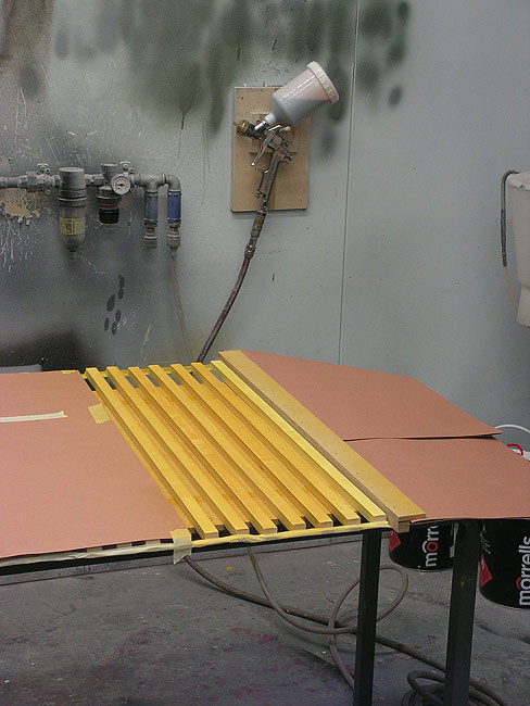
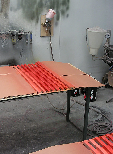
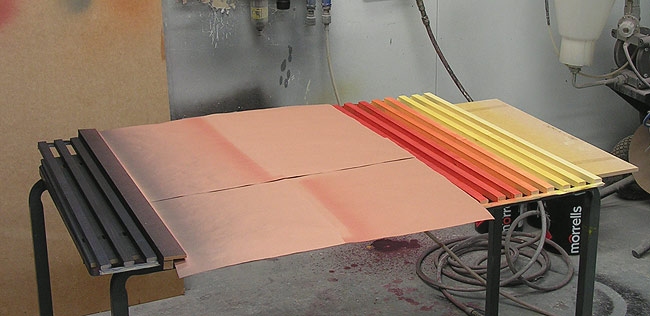
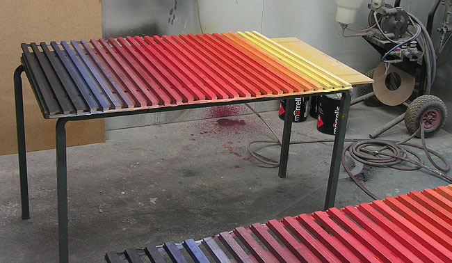
Moving
on from the image above which showed the first dying stage, it can be
seen in the image below that the protective L shaped piece of MDF and
pieces of brown card were rearranged whilst additional dying had been
undertaken. As you scroll through the subsequent images this method of
moving protective card and L shaped MDF pieces as the dye colour is
adjusted continues until the job is complete. The method used to adjust
the dye colour was simply to assess what effect each application of dye
had on the wood and adjust colour as required. For instance, I wanted
to change from yellow to orange to red so, employing those proven
methods of ultimate control in work, sometimes known as "by the seat of
the pants" method (sic), I used my instincts and a 'best guess' technique
which informed me when to add a bit of red to the yellow already in the
gun, and when to get rid of the yellow altogether, etc to achieve the
graduations in colour.
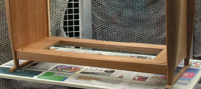
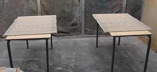
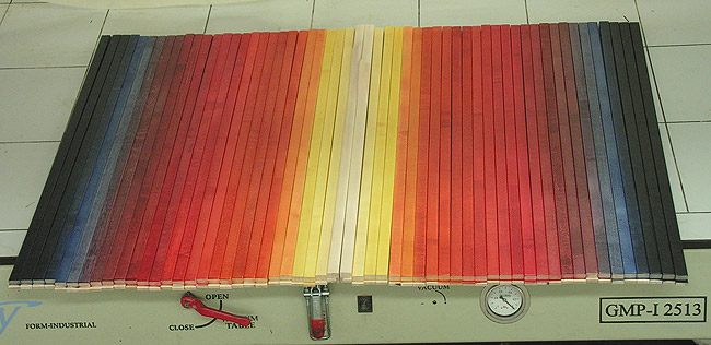
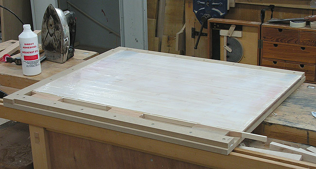
Finally,
in the image below all the staves had been dyed and polished with two
coats of 30% sheen pre-catalysed lacquer, rubbed down between coats
with 400 grit abrasive paper to remove nibs and dust specks. Here, they are simply laid out on a flat surface to indicate their final appearance.
Tambour Assembly and Final Fitting
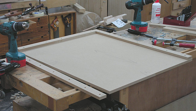
After polishing the tambour slats they have to be assembled, and to do this an assembly board was made out of MDF. Assembly boards need to be exactly square in one corner, and two battens are screwed on to the two edges that lead into the square corner, see below. In reality the other two edges of the assembly board don't need to be square or particularly accurate, but with a sliding table saw it's simple enough to just make the whole board square.
After polishing the tambour slats they have to be assembled, and to do this an assembly board was made out of MDF. Assembly boards need to be exactly square in one corner, and two battens are screwed on to the two edges that lead into the square corner, see below. In reality the other two edges of the assembly board don't need to be square or particularly accurate, but with a sliding table saw it's simple enough to just make the whole board square.
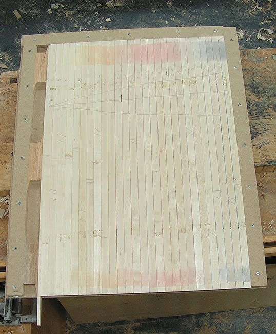
How
an assembly board works is that all the tambour staves are
jammed into the square top right hand corner as shown in the image
underneath. On the left hand side there is another batten fixed firmly
to
the assembly board and six folding wedges provide pressure that clamps
all the staves tightly together. As long as the staves are tight in the
right angled corner of the assembly board (up against the screwed on
battens) then, all else being equal, the stave assembly is square and
ready
for the attachment of the canvas backing. Note the cabinetmaker's
triangle
marked in pencil on the back face of all the staves. The purpose of
this is to ensure they are assembled in the right order. For instance,
if all the parts had been moved around for some reason and become
disordered, then reordering them is easy through just putting the
triangle back together correctly. With two tambours in this
cabinet, and a lot of staves, one triangle was needed for each
assembly. Ensuring the position of the triangle on one assembly
is quite different to the position and form of the triangle on the
other, if staves do become muddled up it's relatively easy to
sort
everything out if necessary.
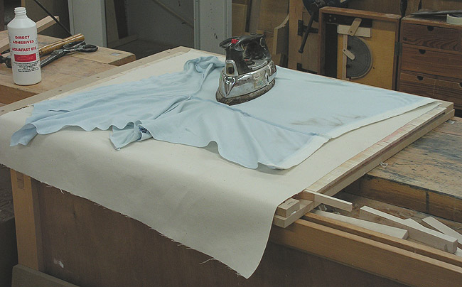
Attaching
the canvas to the staves required spreading glue onto the wood, in this
case PVA glue, but other glue types are just as good, placing the
pre-cut canvas carefully in place, and applying gentle heat with an
iron through a protective cloth. This protective cloth -- blue here, prevent possible burning of the white canvas backing.
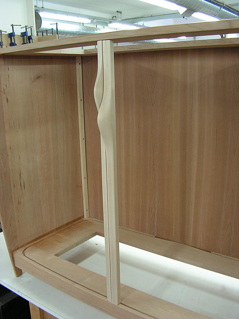
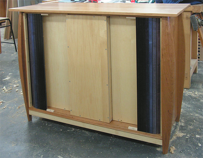
After
gluing on the canvas to the tambour staves, a test fit of the tambours
followed, see below. All worked well at this point and
construction of other parts of the cabinet continued until final
fitting of the tambour near the end of the job.
A
means is required to operate the tambours, ie, to open and close them,
and various types of finger friendly profiles, shapes, or holes, etc are suitable. A typical
method is to make use of a canvas locking stave and create a protruding profile
that can be grabbed or pushed with the hand. The locking stave is the
last stave attached to the
canvas backing which holds together all the rest of the staves in the assembly. The finger friendly mouldings used on the locking stave
protrude towards the open front of the cabinet, and because of this
protrusion these staves can't pass all around the tambour
groove, especially where the groove passes close to the cabinet side
(in this case). The method of attaching the locking finger stave is
illustrated below. The inside of the stave is machined to create a
rebate into which a bead is screwed into place. This can be seen
on the right side of the picture and it can also be seen that the
canvas backing is trapped in the rebate by the bead. To the middle left
of the picture is the unassembled second locking stave and bead for
this specific cabinet.
All that remains to do is to remove the screwed on bead from the locking stave, slip the tambour into its groove at the back of the cabinet, and push the tambour around to a convenient spot. Next, working from the back of the cabinet, the locking stave is reattached to the rest of the tambour by refitting the bead and trapping the canvas, and the canvas cut flush with the back of the locking stave to leave a clean finish on the inside.
All that remains to do is to remove the screwed on bead from the locking stave, slip the tambour into its groove at the back of the cabinet, and push the tambour around to a convenient spot. Next, working from the back of the cabinet, the locking stave is reattached to the rest of the tambour by refitting the bead and trapping the canvas, and the canvas cut flush with the back of the locking stave to leave a clean finish on the inside.
The last small job is creating and fitting stops to prevent the tambour opening too far, and in this case, four small T profiled maple blocks were fashioned and screwed into place. The lower leg of the T profile fits into the tambour groove, and is simply a means of eliminating the very small chance of the blocks rotating in use. They are held in place with a single screw making them easy to remove and replace if the tambour assembly requires maintenance of some sort in the future.
Home Biography Tables, Chairs Cabinet Furniture Beds, Built-ins, Other Work Exhibitions, Galleries, News Articles Teaching and Student Work
Contact
Contact
© 2017 Richard Jones