Home
Biography
Tables, Chairs
Cabinet Furniture
Beds, Built-ins, Other Work
Exhibitions, Galleries, News
Articles
Teaching and Student Work
Contact
Richard Jones Furniture
The Making of the Omega Console/Hall Table Laminated Underframe
Link to studio photographs of the Omega Console/Hall TableThe two main tasks in constructing this table were:
- Forming the front and rear wooden arced frames that connect the table's foot to the rail structure carrying the table top.
- Attaching the foot and the rail structure accurately to the two arced frames ensuring that the bottom edge of the foot was parallel to the top edge of the rails.
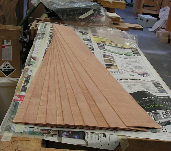
Below. The constructional veneers came in longer and wider lengths to start with, but at this point they had been cut into pieces roughly 140 mm wide because the plan was to split the resultant laminate of the glue up into two widths giving two pieces each finishing at 60 mm wide. Doubling up the width in this way also results in halving the number of glue ups required, which is a time saving technique when pressure needs to be applied for ten or twelve hours, as is the case with slow set epoxy resin when no additional heat is available.
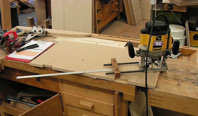
Below. Routing out a pattern or template for the bending form using a hand held router and a trammel.
The template was attached to seven further pieces of 18 mm (3/4") MDF one at a time with a couple of screws ...
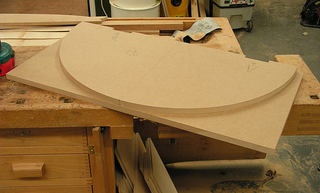
...
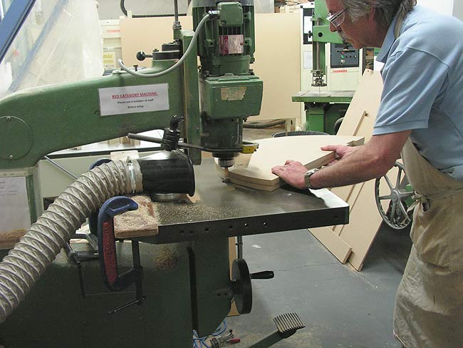
which was bandsawed close to the template's edge and then passed under
an overhead router fitted with a top bearing pattern cutting bit, below.
Below.
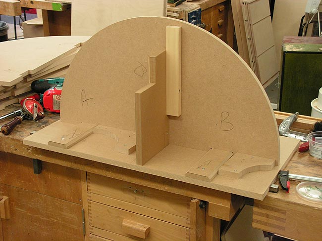
A rig was required to assemble the eight routed pieces that go to make
up the former's width of 144 mm (~5- 11/16"). This consisted of a flat
MDF base, a couple of odd scraps of MDF set to a line running left to
right as viewed, a couple of cross bearers (the two bits of MDF with
bevelled top corners) and a bit of MDF and spare wood sitting vertically to
the base, all carefully set out square and perpendicular to the base
board, and fixed in place with screws. The job of the cross bearers is
to capture a notch cut into the straight edge of the pieces that go to
make up the former.
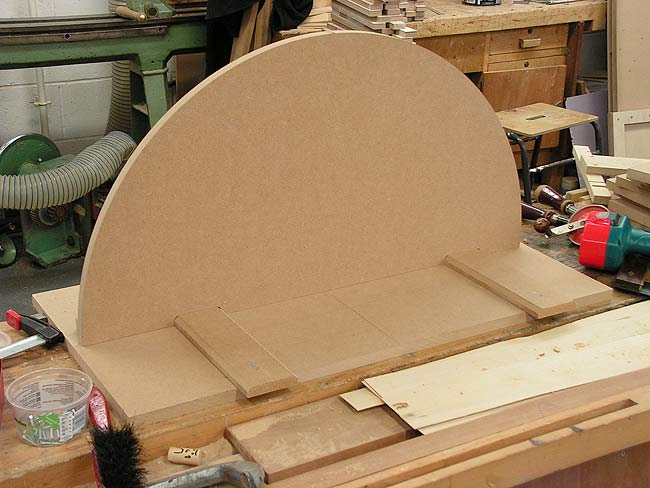
Below. The same assembly rig as above seen from the opposite side.
If you look closely you may just be able to make out a small nipple at
top dead centre of the MDF's arc. This was used to ensure alignment of
subsequent pieces of MDF added to make up the requisite width of the
former.
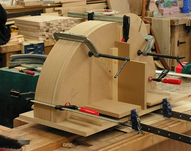
Below.
The completed former simply glued and clamped together on the assembly
rig. Alignment was almost perfect requiring just a little planing to
knock off the ridge of nipples, mentioned in the previous caption, at
the top and light sanding to even out a minor discrepancy or two.
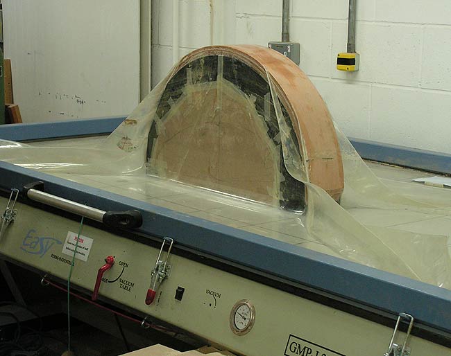
Below.
Plastic sheeting was taped over the former to prevent the laminated
bend sticking to it, glue brushed on to the veneers, which were then
placed over the former already sitting on the platen of the vacuum
press, and a vacuum pulled to suck down the bend.
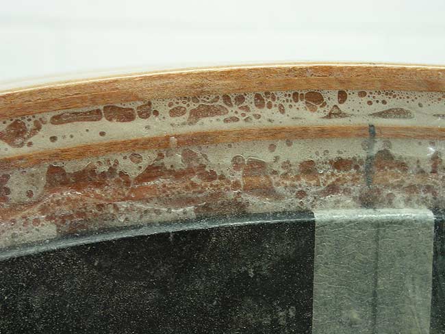
Below. Close up of the glue being squeezed out from between the layers of veneer during pressing.
Below.
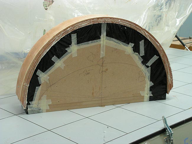
One bend complete after leaving it overnight in the
press. The second bend was done the following night.
Below.
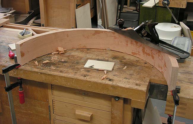
After forming the bend a straight edge was required. This was done with
a No 7 jointer plane, essentially in the same way that a straight edge
is formed on the edge of a straight board by hand. A bit of ingenious
rigging up on the bench was needed to hold the piece involving the
bench dogs, F cramps, and out of sight at the back another couple of
clamps and a piece of MDF with an arc cut in it to roughly follow the
arc of the formed bend. Following this procedure which
was undertaken on both edges, the bend was cut into two widths of 60+
mm on the bandsaw and these sawn edges straightened parallel to the
existing straight edges in a thickness sander which, fortunately, had a
wide belt and feed belt that could accommodate the radius of the arc as
it passed under the sanding belt.
Below.
Moving on, a method was devised to fit the foot and top rail accurately
to the arced frames. The start of this process involved finding a means
to rout an arced groove the same width as the thickness of the curved
arced frames into the inner faces of both the foot and the rails. A
pattern was made out of a piece of 18 mm MDF and a 3 mm
(~1/8") deep arced groove of the same inner and outer radii as the curved frame was worked in it with a
router and trammel.
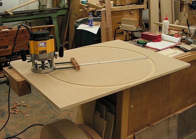
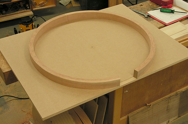

The
internal and external radii of the groove matched the thickness of the
glued up laminations, see image below. This was also the
point at which the two laminated arcs that make
up each of the front and back arced frames were cut to length ready for
the
later operations of fitting them to the foot and the top rail
structure. Notice, for instance, the precise butting together of
the two arced laminations towards the rear of the picture. The gap
between the laminations in the foreground go to the table's top side.

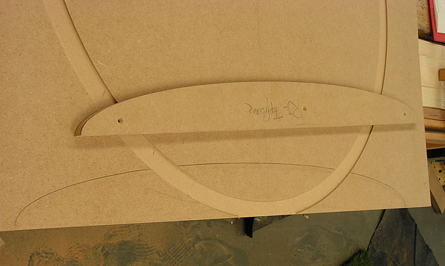
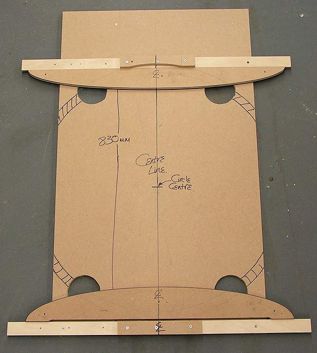
Below. Sitting on top of the grooved MDF is the half elliptical foot template used
to set out its shape and position on the jig, and the
resultant visible pencil mark. The same procedure was used for the top
rail that supports the table top. Marking was done simply by lining up
the straight edge of the template with the straight edge of the large
assembly jig, as well as matching centre lines on the two parts, and
running a pencil around the template.

Below.
The next stage required trimming the MDF on both edges on a
sliding table saw. The edge for the position of the foot was reduced in
width by the height of the foot, i.e., 100 mm and the edge for the top
rail reduced by its height, i.e., 75 mm, thus reducing the the assembly
jig's width to 655 mm from its original 830 mm. Following this
operation the edge of the cherry parts, still rectangular, and therefore not yet shaped to their
elliptical profile, were lined up and butted up against the
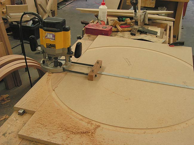
edge of the jig and the two parts clamped together. The router on its
trammel was used again to continue the arc through the cherry parts.
Notice that the eventual shape of the foot (in pencil) can be seen in
between the dust and chips on the near side of the router.

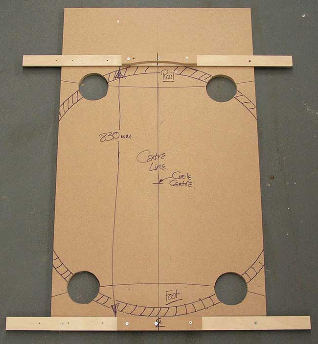
The
following stage is something I forgot to photograph at the time of
manufacture, but I hope to be able to convey the procedure through the
following two images. An assembly jig was made up as below with a piece
of MDF and two pieces of plywood (and other odds and ends) set out as
below. The two plywood pieces are parallel, and spaced 830 mm apart. The hatched ring merely indicates the position of the arced laminated parts.

Below. To illustrate the procedure, here the foot and rail template have been placed where the actual cherry parts fitted.
Arced pencil lines faintly visible on the templates indicate the groove
worked in the cherry parts as seen in the routing procedure two
photographs up. The arced laminations were notched around the
thickness of the cherry foot and rail so that it fitted into the arcing
groove, but the depth of the notch was such that the edge of the
laminations missed the surface of the MDF assembly jig by
roughly 2 mm. The four roughly circular holes in the large base board
were for assembly of the rear portion of the foot, rail and arced
lamination assembly. These holes provided enough room to fit a
screw through both the foot and the rail into the laminates. Being at
the back I didn't mind the fact that the head of the screw would show,
but this will only be the case if the table is pulled away from the
wall it sits against. The front portion of the same assembly was
screwed together through counter-bored holes in the laminations into
the foot and rail.

Below.
The foot partially built and dry assembled. Note the arc of the
shallow groove ready to accept the laminated parts at the later final
assembly.

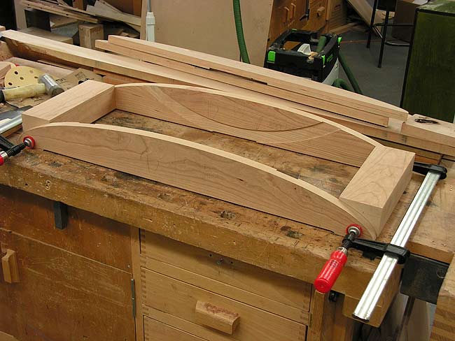
In
the image above two short rectangular cross pieces connect the
elliptical front and back parts of
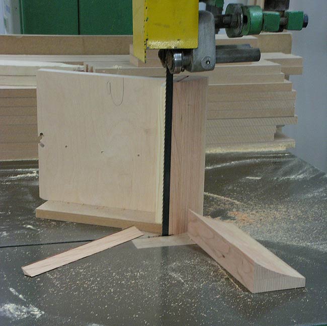
the foot. To save some effort and time hand planing these two short
parts, a few pieces of ply and MDF were cobbled together to make a
right angle jig for the bandsaw table, and the short cross rails were
attached to this jig with a couple of screws thus presenting them
safely to the bandsaw
standing on their end. The bulk of the waste was trimmed off both
pieces using this holder, see below.

Below.
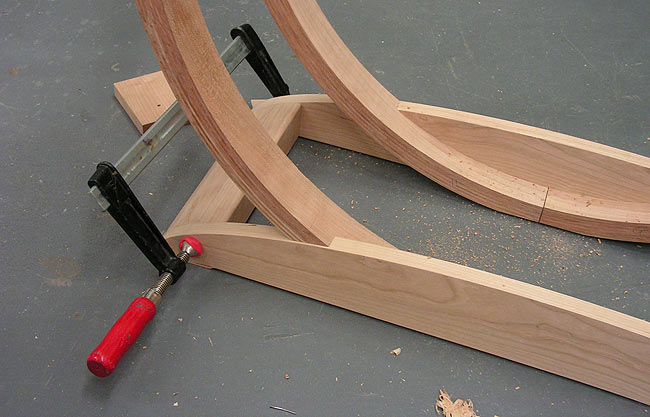
Some final assembly shots. Note that the laminated arc scribed
to the curve of the foot, and notched so that its front edge sits back
from the face of the foot by a couple of millimetres.

Below.
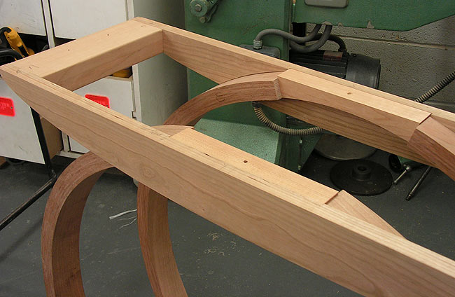
The rails under the the table top have a similar construction to that
used for the foot. The straight pieces spanning between the ends of the
arced laminations serve to both fill in the gap neatly and provide a
place for a screw to pass through to hold the top in place along with
similar screw holes in the short cross rails at both ends of the
framing.

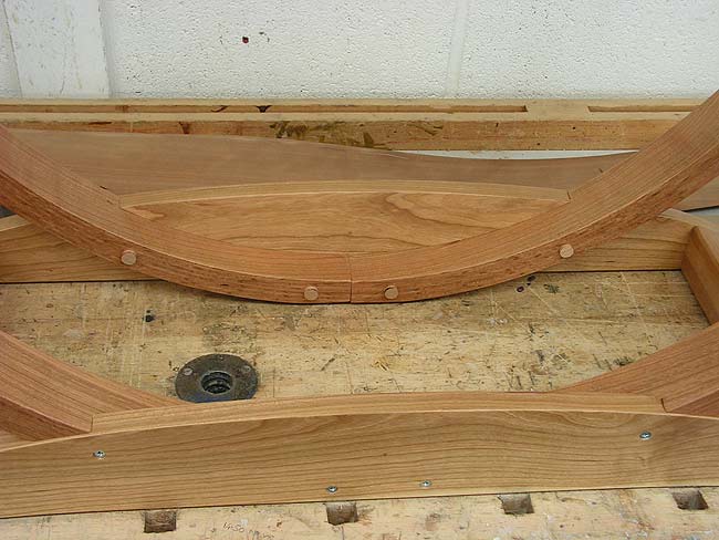
Below.
Screws holding the framework together are clearly visible on the rear
wall facing part of the foot. Similar screws driven in through the back
face of the laminated arc are disguised with pellets, here still
sitting proud of the edge of the lamination, but later flushed off and
polished along with the rest of the table.

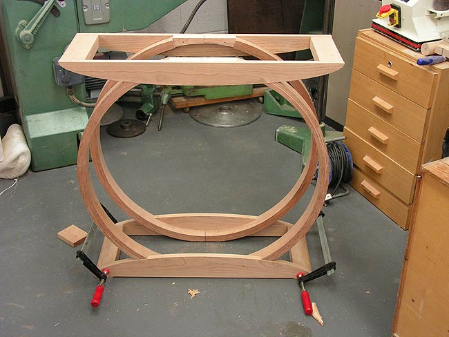
Front view of the dry assembled underframe below, ready for final gluing up.

Home Biography Tables, Chairs Cabinet Furniture Beds, Built-ins, Other Work Exhibitions, Galleries, News Articles Teaching and Student Work
Contact
Contact
© 2017 Richard Jones